AC Current Sensor
SKU: MD0600Couldn't load pickup availability
Share
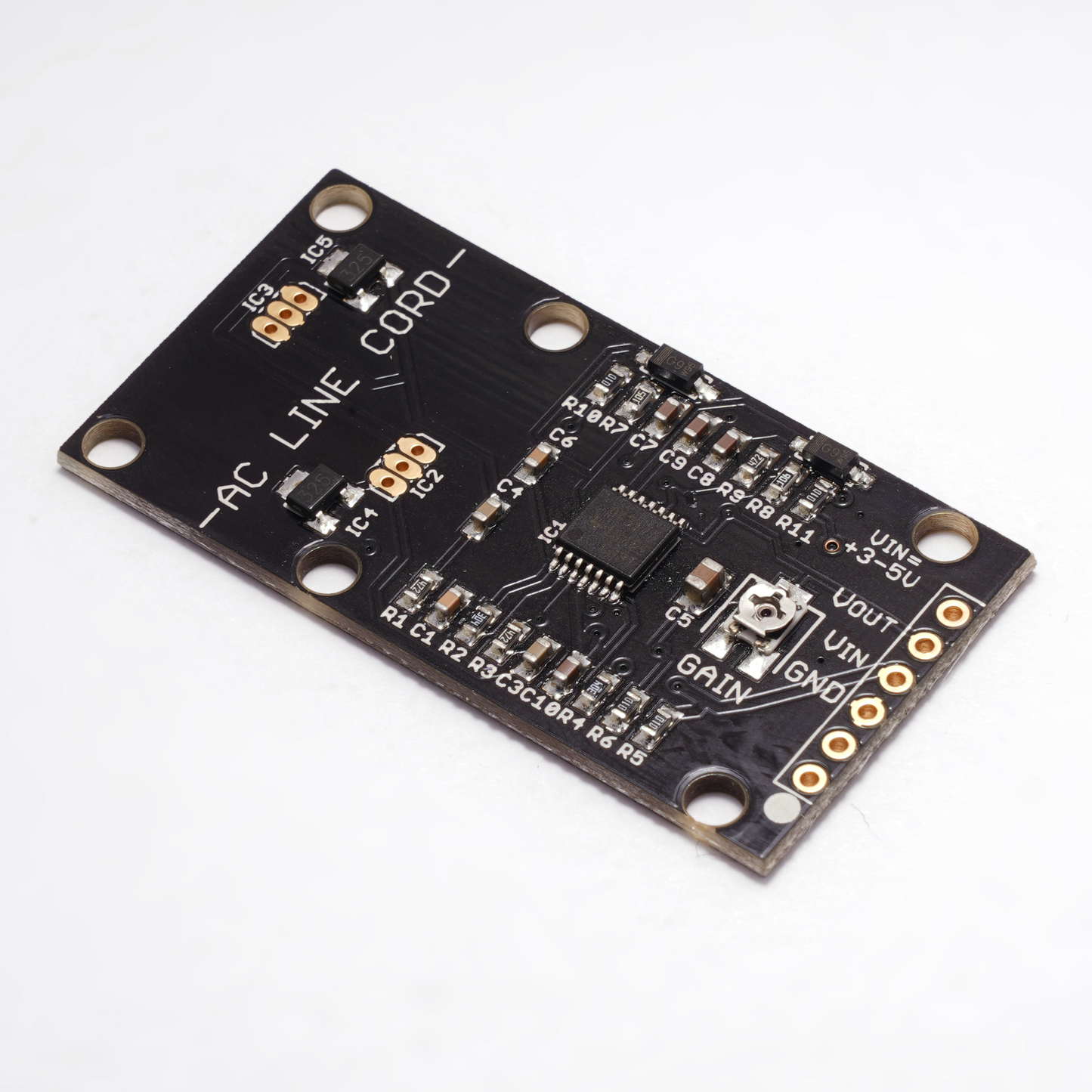
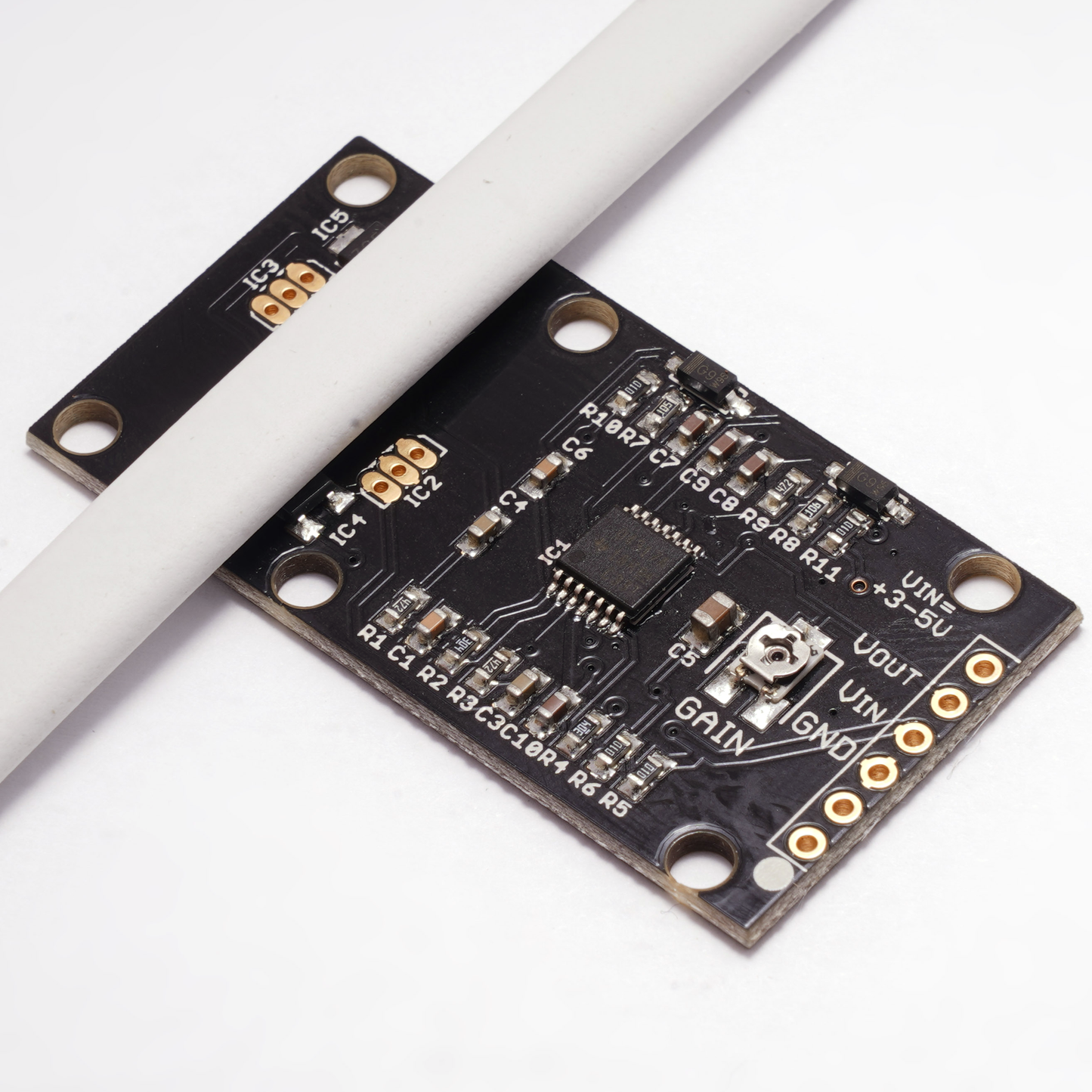
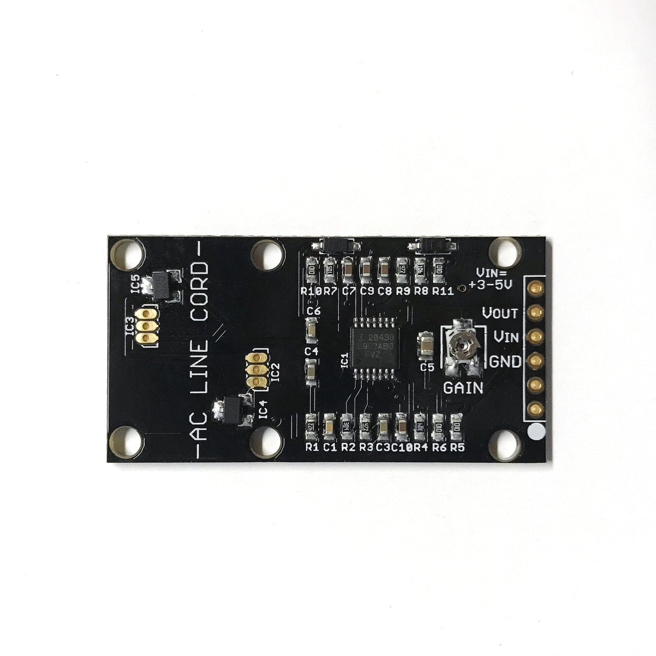
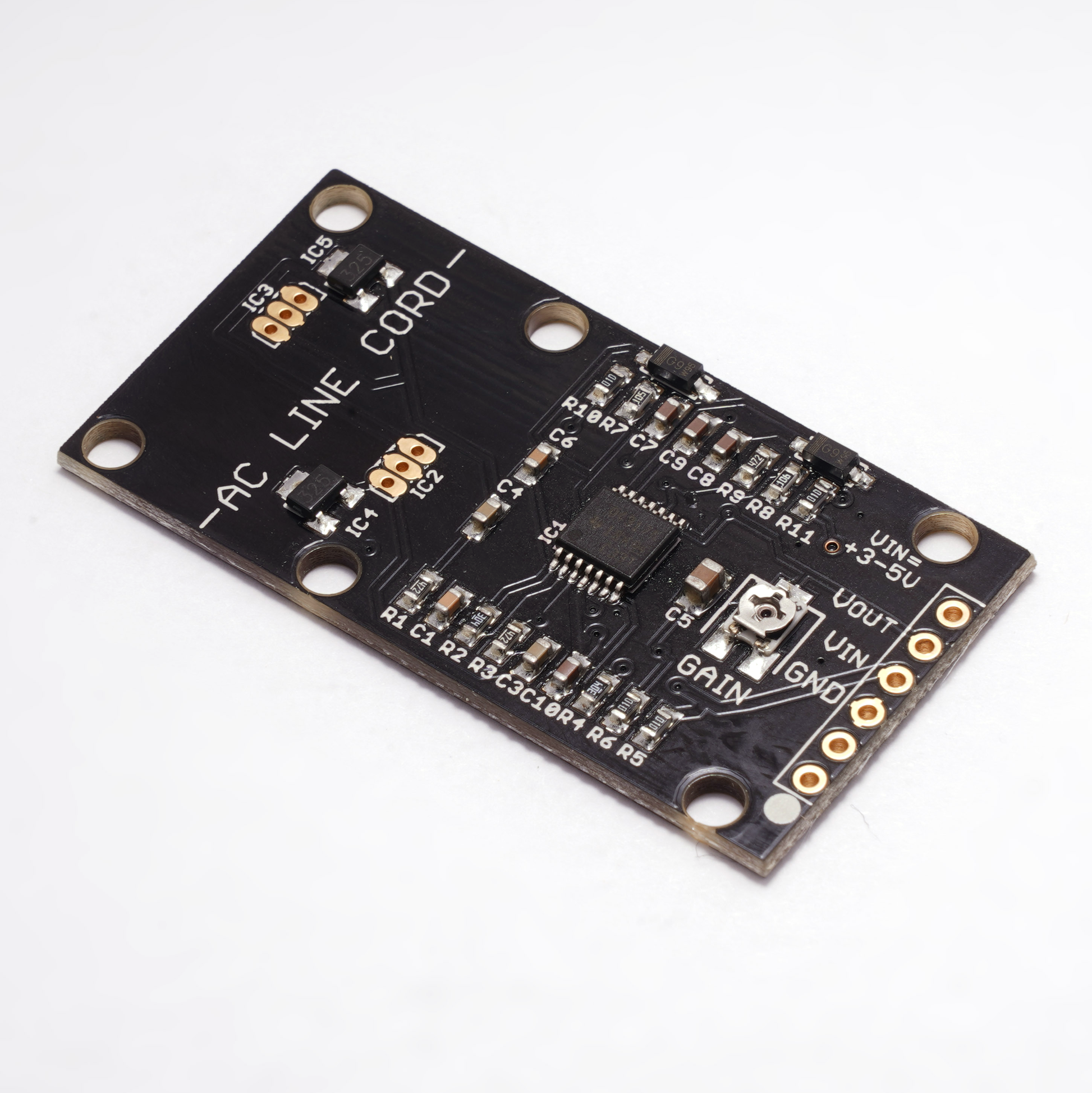
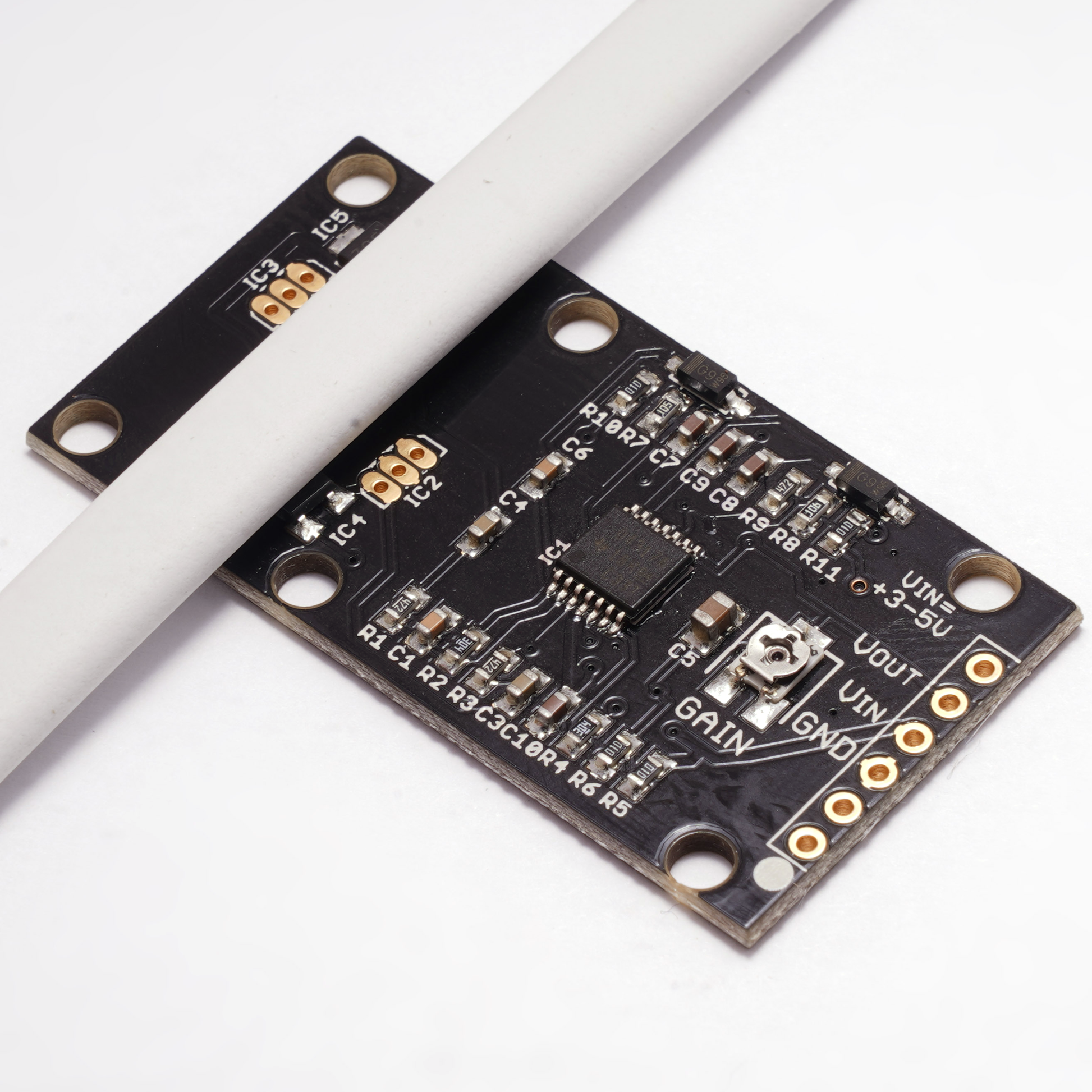
The Modern Device AC current sensor is an absolutely unique, easy-to-use, electrically isolated current sensor for AC mains voltages (120/240 volts AC). Just zip-tie the sensor to a power cord, and safely read the current proportional to the DC output. The sensor only has three connections 3.3 or 5 volts, GND and the linear voltage output that goes directly into a microcontroller ADC (analog pin).
With the sensor being entirely isolated from the AC line cord, the Modern Device Current Sensor is a safe and easy way to sense current with an Arduino or other microcontroller with no fuss. The current sensor can distinguish as little as 2 watt loads at 120 volts, which means that it can sense a change in current of AC current of about 16 mA. The output is just an analog voltage which is proportional to the current sensed. If you are looking for absolute values of current you will need to do a little calibration: this is as easy as applying two loads, hopefully a light load and a much heavier load, and just averaging between the load points.

As our testing shows, the sensor really does have impressive linearity.
How does it work?
It theory you shouldn't be able to sense a current from two AC carrying wires in close proximity. This is because the magnetic fields from the two, 180 degree out-of-phase, power conductors should cancel one another. If you've ever used an AC clamp (current) meter, you know that it is important to put only one conductor inside the clamp. Putting both conductors inside the clamp meter will result in a zero, or very low reading as the fields cancel. The trick the Modern Device Current Sensor uses is getting the two separate hall elements as close as possible to a cables separate conductors, one sensor closer to one wire and the other sensor closer to the other (out of phase) conductor. Applying hall effect sensors which incorporate chopper op amps for high gain, the current sensor then reads the two hall sensors deferentially, which amplifies the difference voltage generated between the two sensors. The sensor can also work well for sensing current in only one wire (hot or neutral) alone if you wish to use it that way, but you will need to orient the wire over only one of the hall effect sensors on the board.
Simple calibration
It is important to note that the actual curve you will get (but not its linearity) is influenced by the geometry of your wire and the sensor's position in relationship to the wire. For maximum sensitivity adjust the sensor's position on the wire while monitoring the output for maximum response. The potentiometer on the board can also be used to adjust the gain by a power of about 3.
A sketch in the blog posts below explains a very quick and simple methods for calibrating the sensor, which only requires gathering two data points. The sensor ships with two small zip ties that can be used to secure the sensor to a line cord, extension cord or power strip, and a 3 pin male header. In some cases you may want to add a drop of hot glue to keep the sensor locked to the wire in a stable configuration. A separate dropdown menu item has extra zip ties available.
| Current Sensor Specifications | |||
|---|---|---|---|
| VCC | Sensor Measured Watts / Amps | Output Voltage Range | Sensor Current |
| 3.3V | 2 watts to 3000 watts | .05V to 2.8V | 11 mA |
| 5V | 2 watts to 3000 watts | .05V to 4.5V | 16 mA |
Resources
- An Arduino sketch for using the Modern Device Current Sensor
- Blog post on the current sensor
- Blog post on calibrating the current sensor
- Blog post the current Sensor at 3.3 volts
- Modern Device Current Sensor Schematic
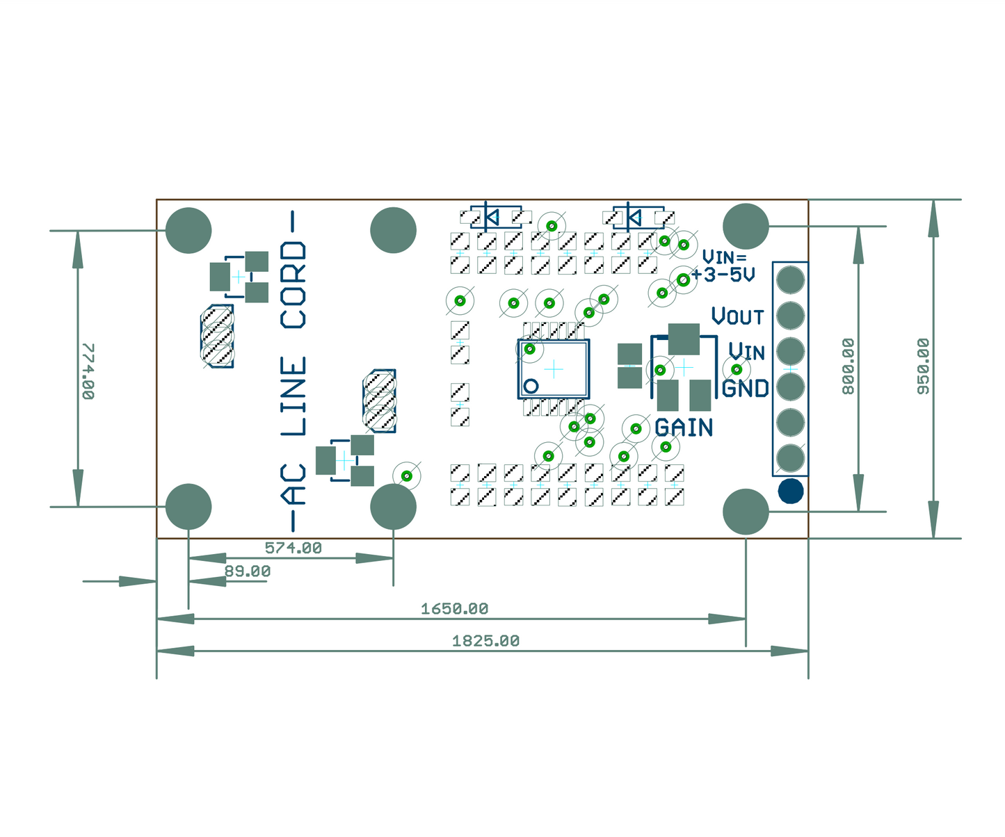
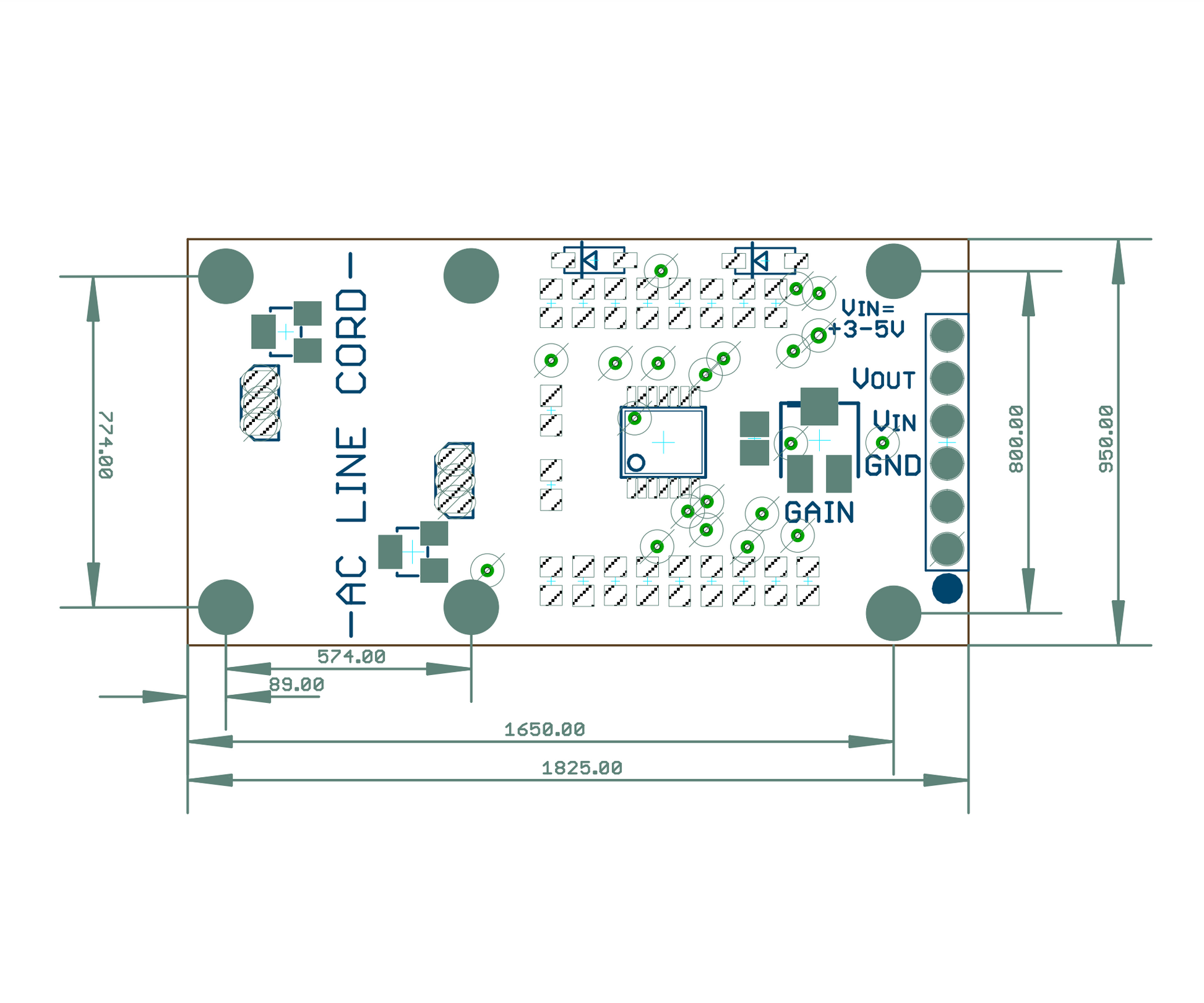
- Modern Device Current Sensor dimensions pdf
- Modern Device Current Sensor.dxf(zipped)
