
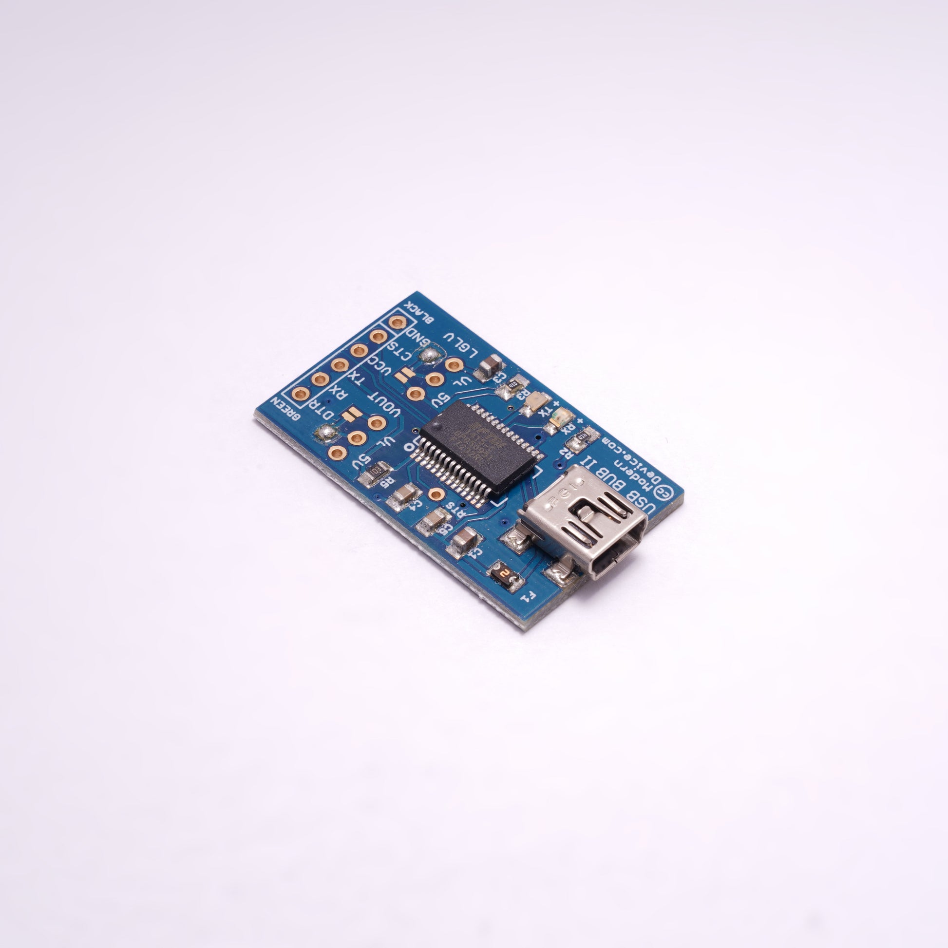
USB BUB 2
SKU:Couldn't load pickup availability
The newer USB BUB III is available here!
USB to TTL serial adapter
The Modern Device USB-BUB is several years old now and we've sold many thousands of them. We decided to spin another FTDI board but not to retire BUB 1. We wanted a board that was slightly smaller, had a voltage option on the power line, and could accommodate an outboard voltage regulator, so customers could easily work with oddball voltages. Jean-Claude Wippler - the master of the Jee universe, also wanted a symmetrical board that would perfectly fit the JeeNode series of boards. We even made it blue, in honor of the Jee Internationale.
Here's a feature list.
- A polyfuse protects the USB line from short circuits and those alarming "USB line is overcurrent" messages.
- Red and green LEDs show serial activity on both the TX and RX lines.
- A shunt and jumper pads (your choice) choose power levels from 5 to 3.3 volts, or an outboard regulator voltage.
- A shunt and jumper pads to switch logic levels from 5 to the FTDI's internal 3.3 volts or an outboard regulator voltage.
- A capacitor on the DTR line to facilitate interfacing breadboard & DIY Arduinos.
The output header is arranged with the same signals as the FTDI RS232 cable (and the same as the same as the BBB/RBBB/LilyPad/Arduino Pro etc, etc) pin header, with the added bonus of having the DTR line instead of having to use the RTS line (with its attendant quirks. The official Arduino schematics also use DTR signal instead of the RTS.
The second socket on the classic BUB was eliminated to accommodate the new power options.
Default Options
The BUB II ships with the 5V power option soldered by default and the 3.3V logic level option soldered by default. This will result with power (VCC) at 5 volts and signal logical levels at 3.3 volts. This works on Optiboot and Decimilia bootloaders on every Freeduino / Arduino board we've tested. If you choose to use the headers and shunts, you'll need to unsolder the solder jumpers before proceeding.
Should you wish to use an outboard regulator, just install a MCP1703 voltage regulator, cut the jumper on the 3.3V option on the back, and solder up the external VR option on the back of the board. The MCP1703 is available in 1.2, 1.5, 1.8, 2.5, 2.8, 3.0, 3.3, and 4V varieties. Be sure to order the SOT-223-3 package. We have the 3.3volt version available here.
Optiboot
Customers using the Optiboot bootloader should solder up one of the Logic Level options (LGLV jumpers on the board). The Arduino Deicimila / Duemilanove bootloader works fine with the logic level pin floating (VCCIO - pin 4 on the FTDI chip) but the Optiboot bootloader does not, probably because of the higher upload speed. The BUB seems to upload with Optiboot with either the 5V or 3.3V option soldered, but will not upload to Optiboot with the option floating (nothing soldered). To add the final caveat - if you use the 3.3V option, you also need to solder up the 3.3V option on the back of the BUB II.
Package Contents
The BUB II ships with a female six-pin header, two male three-pin headers and two shunts for the power and logic level select, that the user may solder on, if desired to facilitate switching logic of power voltages. In reality the default choices of the solder jumpers are going to suffice for most users out of the package.
The logic level is set by solder jumper to 3.3V by default and the power jumper is likewise set to 5V by solder jumper. As a default configuration, most users will probably want to solder on only the female six-pin right angle header.
The BUB II uses the mini USB header. We have it available as an option in the dropdown menu with a 3'USB A to mini-B cable. Other length cables are available on our USB cables page.
Installing FTDI Drivers
The BUB II, like all boards that use an FTDI chip for a USB communications link, needs drivers installed. Download the appropriate drivers for your operating system from this page. Follow the standard procedures for installing drivers. On a Mac, just click on the dmg file and install. With windows you follow the links after the "Found new hardware" message appears. If you're unlucky you'll need to visit the device manager for confirmation or to reinstall.
Once the FTDI drivers are installed, you should see the virtual serial port show up in Arduino -> Tools -> Serial Ports, if you're using the Arduino IDE. It should appear / disappear when you plug / unplug the BUB.
Resources
FTDI VCP (virtual com port) drivers page
Eagle schematics and board design at Github
Schematic in pdf format
Regulators that will work with BUB II at Digikey
